


Problem
The current and strong competitiveness dynamic, the resulting need of reduction in costs and of the qualitative improvement require some extra activities that go far beyond savings.
The REDUCTION IN COSTS itself does not satisfy the medium-long term needs of improvements, especially in terms of maintenance of the qualitative standard of products. It takes creative solutions and ideas to achieve a first-class situation in which reducing costs, constant quality and innovation can be achieved together.
The solution we offer
Here some examples of how, by investing time in the co-design phase, our customers achieved some real and practical solutions in which process cost saving, quality improvement and innovation were reached together.
This proves that a cooperation during the design phase and the exchange of information lead to excellent and long lasting results.
Reduction in the cost of the component by reducing the quantity of raw material used through:
a) optimization of the positioning of the component in the metal strap;
b) structural modification of the component, directly or indirectly – that is a reduction in the costs related to the downstream process, such as mounting costs etc..
EXAMPLE 1
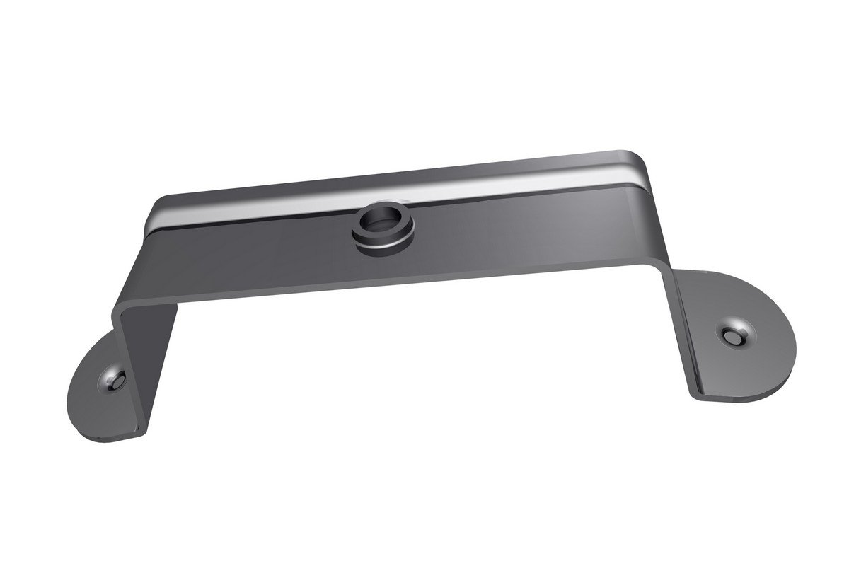
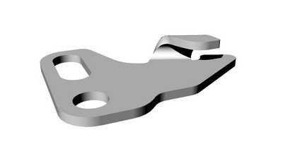
BRACKET (electrical appliance industry):
In this case we have proposed a different design of the component to halve the use of raw material.
Initial situation: stainless steel bracket produced using 74,5gr of raw material
Our proposal and related improvement: bracket obtained using 34,8gr (-53%) raw material with a unit cost savings on the 43%.

* The images shown are for illustrative purposes in compliance with the privacy data protection of our customers. They voluntarily differ from the designed and manufactured product but accurately and faithfully show the solution adopted and the results achieved in terms of design and material optimizations and savings.
EXAMPLE 2
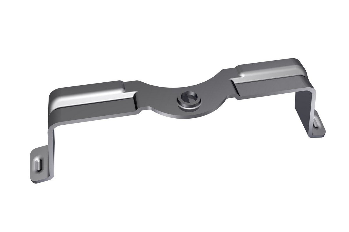
FIXING CLAMP (electrical appliance industry):
In this case we have proposed a slight modification of the process in order to reduce the use of material, and the realization of embossed ribs to increase the structural strength of the component. Furthermore, we proposed a mold capable of automatically stacking the components in output, in order to allow the customer the zeroing of a working phase which required the manual positioning on a loader on board of the machine.
Initial situation: fixing clamp produced using 34,8gr of raw material
Our proposal and related improvement: fixing clamp produced using 24,1gr of raw material obtained with a unit cost savings by 20%.
The change has maintained and improved the structural resistance of the component.
It has eliminated the manual phase of the load of pieces: those are supplied already stacked in dedicated supports.
 * The images shown are for illustrative purposes in compliance with the privacy data protection of our customers. They voluntarily differ from the designed and manufactured product but accurately and faithfully show the solution adopted and the results achieved in terms of design and material optimizations and savings.
The use of raw material can also be optimized by:
- Enhancing the efficiency of the use of the metal strap in single and multiple footprint stamping.
- Using, where possible, lower thicknesses.
- Modifying, where possible, the processing of the component on the metal strap.
- Using alternative raw materials with the same functional performances.
- Using alternative materials that significantly reduce the incidence of the costs of surface galvanization, heat treatments and coatings.
ELIMINATION OF MANUAL OR SEMI-AUTOMATIC PROCESS STAGES
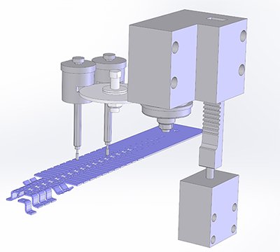
ROLL THREADS TO TOOL (A TAPPING UNIT IS PART OF THE PROGRESSIVE STAMPING TOOL)
This type of optimization eliminates manual or semi-automatic process phases such as threading. The component is stamped and threaded in a single fully mechanized phase. The quality standards are excellent.
The saving is of about 70%.
* The images shown are for illustrative purposes in compliance with the privacy data protection of our customers. They voluntarily differ from the designed and manufactured product but accurately and faithfully show the solution adopted and the results achieved in terms of design and material optimizations and savings.
DRILLING OR FOLDING UNDERCUT MADE BY KINEMATIC MOTIONS OF THE PROGRESSIVE TOOL
This type of optimization eliminates manual or semi-automatic process phases such as threading or complex folding. The mold is equipped with progressive kinematic bending, calibration or horizontal drilling.
EXAMPLE 1
ROD FORK (electrical appliance industry):
undercut bending realized through a calibration and bending kinematic motion.
* The images shown are for illustrative purposes in compliance with the privacy data protection of our customers. They voluntarily differ from the designed and manufactured product but accurately and faithfully show the solution adopted and the results achieved in terms of design and material optimizations and savings.
EXAMPLE 2
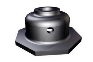
DRAWN CUP (oil hydraulics – mechanics industry):
through hole on the side made with kinematic motion. Before this solution, the component was obtained through sintering at a much higher cost.
* The images shown are for illustrative purposes in compliance with the privacy data protection of our customers. They voluntarily differ from the designed and manufactured product but accurately and faithfully show the solution adopted and the results achieved in terms of design and material optimizations and savings.
The project mentioned below also includes, for of the sub-components, the decision of passing from a coating process done on a frame to the use of a pre-painted component.
The co-design includes proposals for molding/stamping solutions that optimize the cost of the protective coating materials of the component (before or after the stamping). The proposals highlight the potential limits and hidden risks of the process thus improving the quality of the component.
EXAMPLE 1
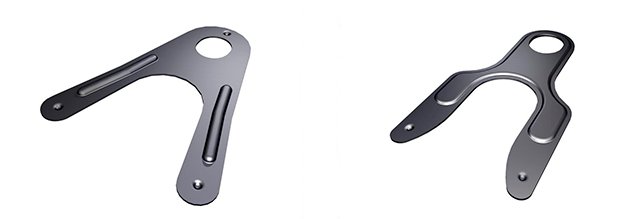
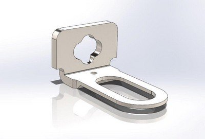
METAL ASSEMBLY (electrical appliance industry):
Initial situation: assembly made by two sub-components assembled in semi-automatic.

* The images shown are for illustrative purposes in compliance with the privacy data protection of our customers. They voluntarily differ from the designed and manufactured product but accurately and faithfully show the solution adopted and the results achieved in terms of design and material optimizations and savings.
Our proposal and related improvement: single component made with a progressive tool, in order to completely eliminate the assembly phase.
 * The images shown are for illustrative purposes in compliance with the privacy data protection of our customers. They voluntarily differ from the designed and manufactured product but accurately and faithfully show the solution adopted and the results achieved in terms of design and material optimizations and savings.